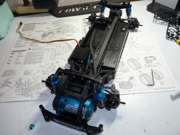
For a Motor system, I ended up deciding to run the 17.5 Murfdogg Synergy motor that I used last year in my 2wd short course truck. I know this motor makes plenty of power to move this little car. I was going to run a 13.5 Novak SS motor (which have a non-removable sensor wire). I test fitted it and the sensor wire would have not reached the box that the ESC is mounted in. I wound up using the Murfdogg, paired with a long sensor wire I had on hand. A bonus is that this motor is almost a dead on match for the Tamiya blue anodizing, and looks like it was made for this car.
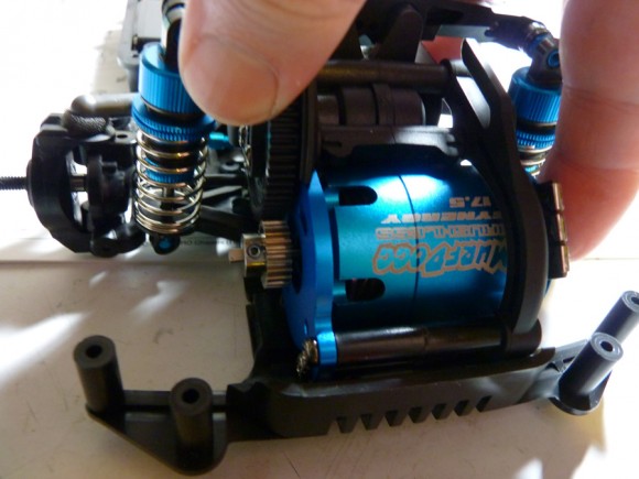
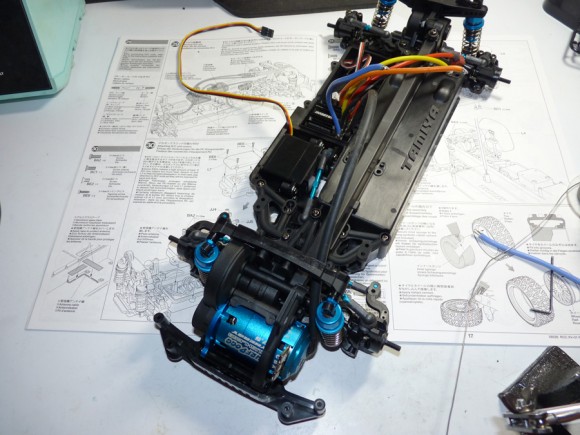
A quick pinion install to set the gear mesh and mount the motor. The motor actually slid right in without having to remove that front shock as I was worried about earlier.
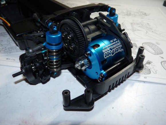
Now the motor is fully secured.
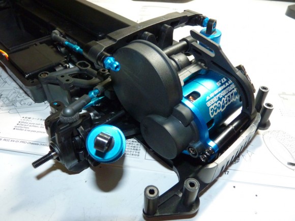
We then install the gear cover. For this, we have to pop the top mount of the other shock off to be able to access the area.
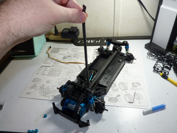
This is my super long sensor wire.
As you can see, it will safely reach into the ESC box.
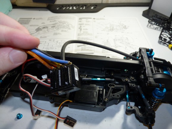
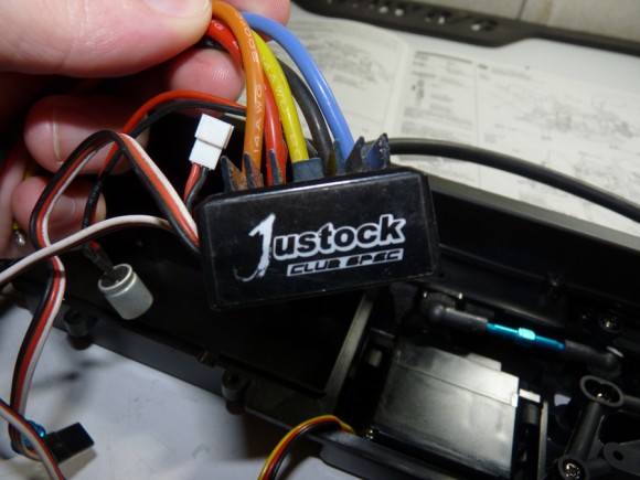
For an ESC unit, I went with the Hobbywing Justock Club Spec. It is a basic brushless speed control that will run sensored motors. It is designed for spec racing and does not have the ability to add timing boost. It has a very small footprint though, and is what I needed to be able to fit it into the box. I had others I was going to try, but they were just too big, like the Castle Creations Mamba Max Pro, will NOT fit in the box without modifications.
Looks like it’s time to do some soldering!
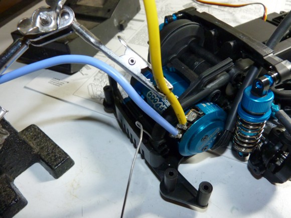
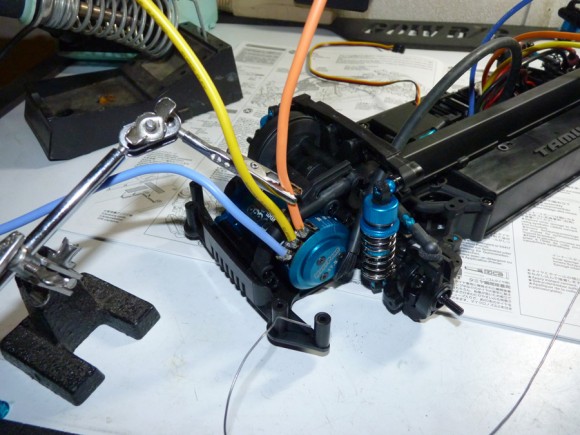
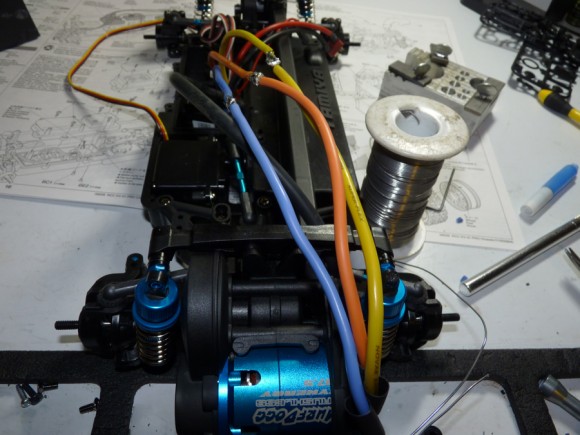
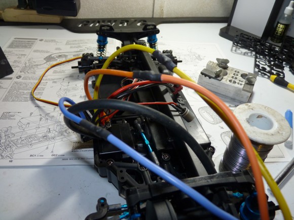
I started by soldering some long lead wires onto the Murfdogg 17.5. These are Novak wires. I used a 3rd hand tool to help hold them in place while soldering.
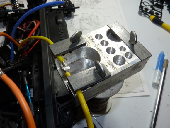
Since the ESC did not have bullet connectors (at least when I got it, it’s on loan from fellow Soup writer, Jim Decker). I decided to direct solder my leads to his. The wire length to meet the front mounted motor is pretty impressive. It’s a LOT of wire! For this I used my KillerBeeCNC Soldering Jig. This allowed me to quickly and easily mate the 2 wires.
All 3 wires are now securely soldered.
Before soldering up those joints, I slipped a piece of heat shrink over each wire. Now is the time to apply heat to them and protect our solder joints from touching one another.
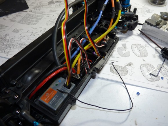
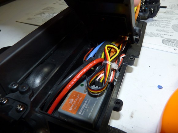
Next we install the receiver, in this case, a Spektrum SR3000 I had laying around.
We then work on tidying up this mess of wires. Even using a small esc, and average size receiver, there is definitely not a lot of room in this electronics tray.
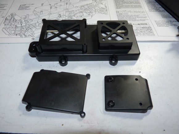
Here is the tray cover. If you are running a hot setup, you can run them without the top pieces for extra ventilation to the ESC. For now, I am leaving the cover off the receiver side to allow heat out until I know if the ESC will run hot.
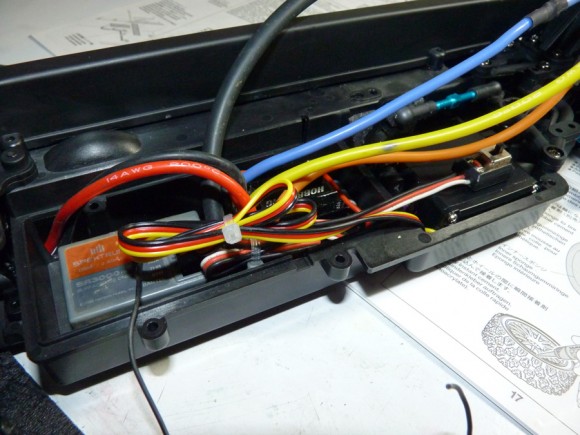
Just to give you an idea of how little room there is. all the wires need to be laid down over the esc in order for them to make it out the small gap in the cover.
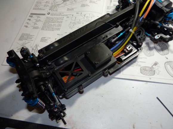
Cover is now installed and you can see where all of the wires come out. I organized them nicely and zip tied them. I also mounted the switch to the servo.
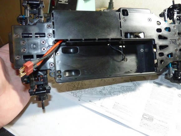
During the ESC install, you have to run the battery lead into the battery compartment. Having the lead just long enough might prove to be advantagious. I think with a lead as long as the one I have will cause issues. I did a test fitment with a Venom Lipo I have that replicated the dimensions of the older Nimh style stick packs, and it fits just fine.
I also tried a top port lipo, and that works too. You need to have an extremely low profile lead wire on the lipo (one where the wire comes off the banana plug at a 90 degree angle, and a short battery lead) but it will fit.


 October 7th, 2012
  Kevin
Kevin 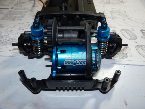
 Posted in
  Tags:
Tags:
Hi, nice build. I just did mine but located the ESC at the rear instead as there is more room under the cover there, had no problem fitting the mamba Max in there. This also gives more room for the wires exiting the cover.